Getting Started with the ESP8266
It’s been two months since I decided to buy a few of this tiny devices from AliExpress. They have a built-in WiFi module and they can be programmed from Arduino IDE. And they arrived this week. 😄
So, after they joy of finally touching with my hands what I had been waiting for so long, the first question came to my mind… How do I actually program it?
Programming the ESP8266 ESP-12F
Install the Arduino IDE and ESP8266 integration. Link to the latest version is at the moment http://arduino.esp8266.com/stable/package_esp8266com_index.json, copy-paste it in the boards manager.
Note: you can find the boards manager configuration at File » Preferences » Additional Boards Manager URLs. After pasting the link, you can install the board from Tools » Board: “Arduino” » Boards Manager… » esp8266 » Install.
And now comes the challenge: there is no USB port and it doesn’t tolerate 5V. So how can we connect it to the computer? And how can we power it?
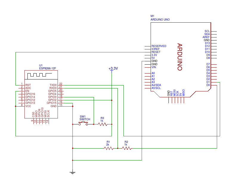
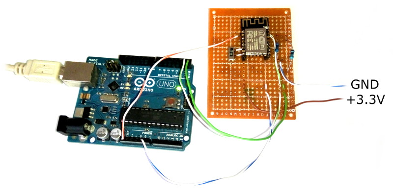
Fortunately I have an Arduino Uno that can be used to program the ESP8266. The builtin 3.3V voltage regulator is not powerful enough to power the chip, so we need an external power supply. Just connect according to the following table.
Note: either remove the ATMEGA chip from the Arduino or flash something “inhert” before connecting the ESP8266; we don’t want random serial data to flow between the devices. I flashed the Blink sketch and everything worked, but anything that doesn’t use the serial port should be fine.
| ESP8266 ESP-12F | Arduino | Power Supply | Notes |
|---|---|---|---|
| RXD0 | RX | Through resistive voltage divider | |
| TXD0 | TX | ||
| GPIO0 | Switch to GND, pull-up to 3.3V | ||
| GPIO2 | 3.3V | ||
| GPIO15 | GND | ||
| GND | GND | GND | |
| RST | RESET | To use Arduino built-in reset button | |
| EN | 3.3V | ||
| VCC | 3.3V |
Warning: RX pin on the Arduino outputs 5V. The ESP8266 only accepts 3.3V, never connect the RXD0 and RX pins directly!
Note: RX pin on the Arduino is actually the TX pin for the computer, and TX pin is actually RX. If you use a USB to Serial adapter you must swap this pins.
If you don’t have a 3.3V power supply, you can use two 1.5V AA batteries in series.
Testing ESP8266 From The Serial Port
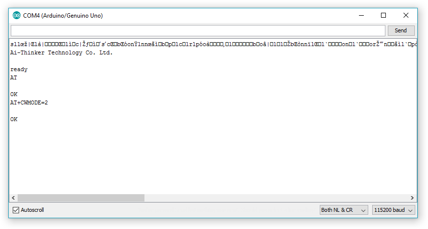
Before proceeding any further, you should test your device by setting GPIO0 to high (3.3V) and opening a serial console to your Arduino (Tools » Serial Monitor from the Arduino IDE). You will be “talking” to both the ATMEGA (if still connected to the board) and the ESP8266, but the ATMEGA will not reply.
Set baud rate to “115200 baud” and new-line mode to “Both NL & CR”.
Note: boot message is transmitted at 74800 baud, this is the reason you get some garbage before useful information while listening at a different rate.
Check if everything is working with the AT command. The ESP8266 should reply with “OK”.
1
2
3
AT

OK
Note: if ESP8266 replies with “ERROR” or doesn’t reply at all, you should stop and check your voltages and settings. Are all connections good? Is RXD0 pin at about 3.3V? Is TX pin at 3.3V? Did you set new-line mode to “Both NL & CR”?
Enter Access Point mode with AT+CWMODE=2.
1
2
3
AT+CWMODE=2

OK
Set the access point to be an open access point on channel 5 with SSID “esp_test” by typing AT+CWSAP="esp_test",,5,0.
1
2
3
AT+CWSAP="esp_test",,5,0

OK
Enable connection multiplexing with AT+CIPMUX=1.
1
2
3
AT+CIPMUX=1

OK
Enable test TCP server on port 80 with AT+CIPSERVER=1,80.
1
2
3
AT+CIPSERVER=1,80

OK
You can check ESP’s IP address with AT+CIFSR command. It will always be 192.168.4.1 in access point mode.
1
2
3
4
5
AT+CIFSR
+CIFSR:APIP,"192.168.4.1"
+CIFSR:APMAC,"5e:cf:7f:2b:8a:8a"

OK
You can now search for WiFi networks from your phone. “esp_test” network will be visible. If you open your web browser and visit http://192.168.4.1/ a message will appear on the serial console… that’s an HTTP request.
1
2
3
4
5
6
7
8
9
10
0,CONNECT

+IPD,0,311:GET / HTTP/1.1
Host: 192.168.4.1
User-Agent: Mozilla/5.0 (Android 5.1.1; Mobile; rv:51.0) Gecko/51.0 Firefox/51.0
Accept: text/html,application/xhtml+xml,application/xml;q=0.9,*/*;q=0.8
Accept-Language: en-US,en;q=0.5
Accept-Encoding: gzip, deflate
Connection: keep-alive
Upgrade-Insecure-Requests: 1
Before connection times out, you can reply with AT+CIPSEND=0,6 command, followed by a 6 bytes message.
1
2
3
4
5
6
7
8
9
AT+CIPSEND=0,6

OK
> banana
busy s...

Recv 6 bytes

SEND OK
Your message will appear in the web browser as soon as you terminate the server with AT+CIPSERVER=0.
Uploading a Sketch
Set GPIO0 to low (GND), power your ESP and connect your Arduino to the PC.
Launch your Arduino IDE and load the Blink sketch from File » Examples » ESP8266 » Blink. If you have an ESP-12 model you will have to replace LED_BUILTIN with another value; use 12 for GPIO12 pin.
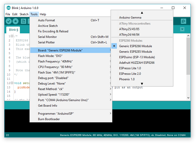
Set your board settings according to the following image…
Tip: you might want to enable “compile” and “upload” output from File » Preferences » Show verbose output during: » compilation; upload.
Now compile and upload the program, and keep your finger on the reset button on the Arduino board… tap it as soon as the message changes from “Compiling sketch…” to “Uploading…“.
Note: only tap the reset button once, do not tap it twice or the upload will fail.
You can check if everything worked by pulling GPIO0 high; resetting again; and probing GPIO12 with a multimeter. It should keep jumping between 3.3V and 0V every second.
Next Steps
Now have an ESP8266 programmer with serial connection. You can start playing with the examples and build your very own IoT device.
Tip: the ESP8266 comes with built-in WiFi, it can join your home network and can be controlled from your computer with just the web browser. That’s for less than 2€ (in both the price and the size of the coin), how cool is that?
Do you want to buy an ESP8266 yourself? Search for “ESP8266 ESP-12” on Amazon.com (faster in the US), Amazon.de (faster in Europe) or AliExpress (cheaper everywhere).
If you have any question regarding the circuit and the procedures, feel free to ask in the comments section below. Thanks for reading! 😁